how to draw 3d weave pattern

In this quick tips tutorial nosotros're going to await at how to create a weave pattern using RailClone. It's a common pattern that has many applications, mayhap most usefully natural fences and baskets, merely for this instance we've taken inspiration from a C18 Architekten who renovated the barrel ceilings of a chapel by cladding it with woven wicker. Along the style we'll demonstrate some tricks for creating repeating patterns on the Ten and Y axis using sequence operators, how to mirror and reuse geometry, and how to dissever a style into more than one generator.
Base Objects
Segments
For this tutorial I'chiliad going to borrow some terminology from cloth making. When weaving there are two types of thread or yarn Warps are vertical threads, that would commonly exist held in tension on a frame or loom. Woven alternately over then under these are horizontal threads called wefts. The aforementioned is true if you're weaving wicker, straw or any other materials. These two elements - warps and wefts - are what we need to simulate to create a woven style in RailClone.
As always when working with RailClone, the aim is to manually model as little as possible and for this example we could get away with only two segments, one for the horizontal weft, and another for the vertical warp. For the latter though in order to create a piffling more natural variation we will use 4 variations. This are very simple, created using just a spline and a Sweep modifier

For the vertical sections (warps), a simple directly spline is enough as long as there are enough edge loops and so that it can be plain-featured to follow a bend if needed.
For different types of construction fabric yous can easily employ a different cross department with the sweep modifier, but fifty-fifty and so this geometry is very easy to create. The simply other thing to note is that the pivot on the Z axis for all the segments is positioned then that segments align correctly, and that they volition tile along the Ten axis when mirrored and repeated.
Splines and orientation
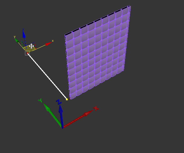
On to the splines, as we're creating a 2 dimensional array, and because the roof will exist curved on the Y axis, we need two splines. The easiest style to create splines for the A2S array is to utilize the top or perspective viewport. In this demo we'll create them as follows:
- Spline 1 should exist straight along the 10 axis. This volition exist used to define the length of the assortment.
- Spline 2 should exist straight along the Y axis. This volition be used to ascertain the summit of the array.

The Ten Spline is pretty piece of cake to understand as it defines the path of the assortment. The Y spline defines the shape and orientation of the array on the Y axis, and has the potential to crusade more confusion. In RailClone 3 we've made this a little easier to empathise - the length and path of the array on the Y centrality is defined by the shape of the array as defined on the Y/Z plane. If y'all rotate the spline sub-object around the 10 axis, yous will run into the arrays orientation updates accordingly.

In RailClone 2 the X/Y plane was used to define the Y axis of the array and this tin can be a little more than disruptive because in club to change the orientation of the assortment in RaliClone 2 you would rotate the spline sub-object around the Z axis.
RailClone 3 actually has a new option that allows y'all to pick between the new more than intuitive settings or to employ the legacy behaviour if you prefer information technology, or you lot need to maintain compatibility with old styles

Creating the fashion
Creating warp geometry
Information technology often makes sense to divide a style across multiple generators. In this case nosotros'll create two, ane for the vertical elements, and a 2d for the horizontal elements. If nosotros were to endeavor and combine these into a unmarried generator the elevation of the warp segment would demand to match the elevation of the weft segment which would significantly add to the number of instances produced. In addition the vertical elements would create a gap between the vertical ones,rather than allowing them to go on as though they are a unmarried thread. By separating them into two generators, both these issues can be easily resolved.
To create the first generator:
- Create a new A2S Generator. Name it Warp.
- Create a new Spline node and wire it to the Generator'due south X Spline input. Go to the Properties panel, click the spline select button and pick the 10 Spline nosotros but created from the scene.
- Create a second Spline node and wire it to the Generator's Y Spline input. For this 1 we'll pick the Y Spline.
- Create a new Segment node. Go to Properties and pick the warp object from the scene.
- Wire the Segment node to the X Evenly input. This will add together vertical segments at regularly spaced intervals.
- Change the Segment's Z Alignment to Eye
- The altitude between warps is controlled by the Properties > Rules > X Evenly > Distancevalue. To make these easier to change later on nosotros can make this value accessible from the Alter panel. To do that, correct-click on the generator and go to Export Parameters. Select X Evenly > X Evenly Distance and a new parameter input will appear at the bottom of the Generator node.
- Create a new Numeric node. Wire it the X Evenly Distance input and rename the node Warp Distance . If yous look at the Backdrop rollout in the Alter panel you volition meet that this parameter is now attainable and can be edited without needing to open the style editor. Enter a value of 10cm for now.

Below is the finished graph for the warp elements. And so far and then good!

Creating weft geometry
The weft geometry needs to lucifer the same.
- Select, copy and paste the existing generator. Because the two generators share the same spline and numeric inputs, they will ever remain perfectly synced.
- Change the generator'due south Deform > Default mode to Calibration. In this way a single segment volition be scaled betwixt the evenly inputs.
- The warp segment is notwithstanding continued to the X Evenly input. We tin can't just delete information technology because we need a segment in this input to ensure that the weft segments are scaled exactly betwixt the evenly distances. The easy solution is to create a new Segment only don't select any geometry. We commonly call these zero segments and they're really useful for adding gaps or forcing RailClone to calculate sure inputs even if no geometry is present. Merely wire this to the X Evenly input, replacing the existing segment.
- Create another new Segment node. To apply the segment's pivot indicate, modify the Alignment > Z property to Pivot

- You should also decide if yous desire the segments to deform. If X spline is straight - as in this example - I would prevent segment'southward from bending by going to the the Deform tab and disabling Curve. If the path is curved I would leave this enabled, simply you should be aware that deformed segment's are not instanced and may increase memory usage.
- In this scene there are 4 weft objects that we'd like to shuffle. Instead of adding each ane manually, right-click on the Segment and click Clone Multiple. An object picker window opens assuasive you to select multiple items. Select weft 1 to iv and click Clone. All the segments will inherit the same settings.

- To shuffle the iv segments, create a new Randomize node and connect the segments to its inputs.
- To create the under - over - nether blueprint, create a new Sequence operator and wire the Randomise operator to the kickoff input. Wire the Sequence operator to the Default input then we tin see how the geometry looks.
- At the moment we're getting a stepping consequence as shown beneath

To resolve this we need to create a version of the segments mirrored forth the X axis, and then alternate between mirrored and normal versions. To practice this create a new Mirror node, and wire the Randomize node to its input.
- Wire the Mirror node to the Sequence node's 2nd input, every bit shown below.

- If you modify the club of the inputs in the Sequence node you'll discover that the under/over pattern can exist offset. This is important because nosotros need to alternate between over and nether on the Y axis besides which tin can be achieved past alternating between 2 sequence operators, one of which has had the order of its inputs swapped. To do this, clone a the sequence operator and swap the inputs. Create another new Sequence operator and wire the 2 existing sequence nodes to its inputs.

- Change the Increment On value for the new sequence operator to Y. Wire information technology to the Default input. You have no created a repeating alternate pattern on the X and the Y axis!

- Optionally you can likewise echo the number of times an input is repeated. To do this, select a Sequence operator and change the Counter values, for example we tin can change the value to 2 for the Sequence operator that creates the pattern on the Y axis to give a different weft pattern.

- Finally you may need to adjust the Z Offset of the warp Generator to make certain it fits correctly into the gaps created by the weave design.
Conclusion
This completes the style. We tin can now reuse it easily past but swapping the splines, for example to create the roof shown at the get-go of this tutorial. Fences, baskets, wicker baskets, trellis and much more can exist created with this technique and the principles of combining sequence operators that increment separately on the Ten and Y axis really is useful for creating all sorts of repeating patterns. If you create any interesting variations on this manner, or you accept any renders created with these techniques we'd love to see them on our forum. Otherwise, stay tuned for our side by side tips and tricks installment and cheque out our other videos in the tutorials section of the website.
This fabric is copyrighted by iToosoft. Yous are gratuitous to link to our tutorials, but if you would similar to reproduce content, in whole or in part, please contact us.
Source: https://www.itoosoft.com/tutorials/creating-weave-patterns
0 Response to "how to draw 3d weave pattern"
Post a Comment